2007 marked the beginning of my more serious tinkering with electronics. Among many other things, it's the year I bought my first pack of bulk LEDs, my first microcontroller, and my multimeter. Thus came to light (haha) my first electronics project:
Here is the long-delayed writeup for this project.
I wanted to start with a common enough project - building an RGB mood lamp. Sparkfun had just come out with their RGB LED bars, so I ordered a pack of 10 strips (30 RGB LEDs total) and set about designing the electronics. In retrospect, I should probably have used a smaller number of high-power LEDs - it would have made it easier to cram all the resulting electronics into the base of the paper lamp - but the LED strips make for a nice, wide, relatively uniform "area light".
As an LED driver, I selected the ULN2803 chip, which simply contains eight channels' worth of Darlington pairs. You can even wire up the channels in parallel to multiply the maximum current throughput.
My first idea didn't even involve using a microcontroller. So I got the chips, some pots, and connected up a simple prototype:
A simple dimmer circuit to try out things.
The red knob was connected to a potentiometer on the unamplified side of the circuit. It formed a voltage divider whose output was amplified by the ULN2803, which in turn drove the LED strip. The multi-turn trimpots you can see in the breadboard were there to adjust the biases and slope of the voltage divider, in order for the circuit to operate in the linear amplification region of the ULN.
Alternative view of the circuit; better view of trimpots.
As it turns out, I rapidly found out that the ULN is far easier to drive in saturation or shut-off mode. (I'm far from being an expert, but I'm guessing Darlington pairs in general probably require some serious care, both design- and application-wise, in order for both transistors to operate in their linear region.) While driving a single LED strip, well under the maximal rated load of the ULN2803, the heat dissipation in the ULN package was sufficient to cause the linear region of the transistors to shift. Thus, without even touching the input potentiometer, the colors on the LED strip would change rapidly and saturate quickly to white, in an uncontrollable fashion. Even funnier, by shooting compressed air at the chip to cool it down, I could get the colors to change back!
An easy way around this was to drive the ULN2803 with a pulse-width-modulated signal. This type of signal is trivial to generate with a microcontroller. (A harder way - for me at least - would have been to build some kind of oscillator whose duty cycle was controlled by a potentiometer, filter the output, and gamma-correct that in analog hardware... but since my analog design skills are quite weak, I opted for the MCU. Plus - programmability!) Coincidentally, with no microcontroller programmer in my possession yet, I had recently ordered an Arduino, and it arrived around the time I made this discovery.
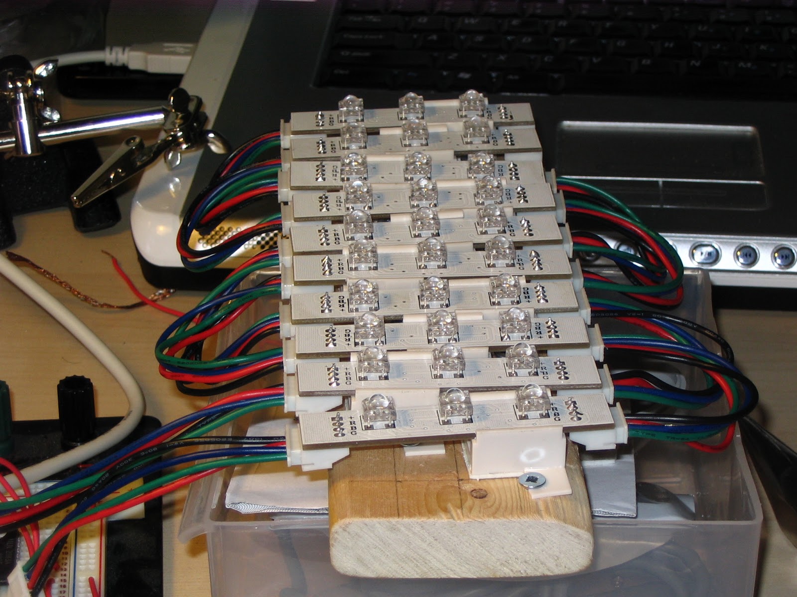
In order to test out things with all LED strips, I buit a little rig to hold them together:
Working out where all the screws need to go to keep the LED mounts in place.
The Arduino, wired to read the RGB pots and drive the RGB LEDs through the ULN2803.
Same.
Close-up of the LED rig.
Power up!
The Arduino setup, with a custom power supply. Nothing too fancy here.
Things seemed to be working nicely, so I moved the ULN to the power supply perfboard. I first planned out the layout using my old friend Paint.NET to make sure things fit properly. (I also use it as a checklist by crossing out traces I've soldered in place. This design is not particularly complex but on more fleshed-out boards it can be a lifesaver.)
Figuring out what goes where.
Lights on!
The final knob wiring.
Moving the ULN2803 to the power supply perfboard.
This was a turning point in the project. Though I felt it was cool to have an RGB mood lamp, I rather thought using a microcontroller simply to do PWM was overkill, even though it was also doing simple gamma curve math to normalize the LED output colors. And I figured, well, it's already part of the system, so what else could I do with it? The first obvious answer was to implement automatic color cycling. I did this and used the RGB knobs to control the brightness, saturation and speed of the cycling.
I also thought it would be really cool to have the lamp respond to music somehow, but I was still a bit analog-shy after being beaten on the head with the topic in school. I began by adding MIDI in support, using a 6N138 optoisolator. I made it so that when Note On signals were received, the LEDs would light up with a brightness related to the volume of the notes. Here's the MIDI In stage schematic. I believe it originated from Tom Igoe's most excellent ITP materials; though I can no longer locate the original page, the schematic is reproduced here.
Arduino MIDI Input stage.
It was very cool to see some interactivity there! But I think what I ultimately wanted was to feed arbitrary music to the lamp. Thus, I decided to wire up an analog signal path and see if I could coax the required signal treatment out of the Arduino to be able to send bass to the red channel, mids to the green channel and highs to the blue channel. Here is the resulting circuit schematic. Once more I believe the biasing portion was somehow gleaned from Tom Igoe's ITP stuff, but I am unable to find the exact original source.
Arduino stereo analog input stage.
This circuit mixes the left and right channels together and biases the whole thing by 2.5V so it centers around the Arduino's analog input range.
Testing MIDI and audio input.
Idem. You can see the breadbord layout with an RBBB Arduino.
More testing.
The rest was just writing software. Conceptually, the analog input stuff is fairly simple. The analog signal is read with 10-bit precision, and is first fed through a very wide high-pass filter to block the DC component. Then, it is fed to three separate IIR filters. The first is a low-pass filter for the red channel; the second, a band-pass filter for the green channel; the last, a high-pass filter for the blue channel. Each filter is "doubled up" on itself to sharpen the rolloff and reduce the overlap between the frequency ranges of each filter. I tuned the filter cutoffs by creating a sine wave patch on my Yamaha DX-100 and feeding that to the lamp to see what color each note triggered.
In practice it took some fiddling to get everything running zippily. Fixed-point math took care of a lot of the performance woes. I also wound up writing a simple custom multiplication routine in assembler to multiply two 16-bit numbers together into a temporary 32-bit buffer, to avoid overflow, then shift back to fixed point before storing the result. (The compiler normally requires 32-bit source values to multiply into a 32-bit destination buffer, but full 32-by-32 multiplies were useless work that wound up being prohibitively expensive.)
I still have the code for all this, and would be glad to share it, but it is far from building on the latest Arduino platform. If there is interest, I would be glad to clean it up and modernize it a bit; just let me know in the comments or e-mail me!
After I was sure everything worked, it was time to embark on the final step of the process... physical fabrication. I think the pictures do a better job than text at explaining.
Final power supply and amplification board.
Laying out the logic and input board.
Final Arduino and input board.
Cutting some holes.
All parts, ready for final assembly.
Cramming everything in there!
Underside.
The boards are held in place with Velcro.
Logic board in place.
Final result - power, mode switch, potentiometers.
Hello! The code is not currently available but I have made a note to clean it up and hopefully post it on GitHub at some point. It uses an extremely outmoded Arduino core and was only ever tested on ATmega168 hardware, but hopefully it's not too difficult to update for 328s.


Wher can I downlod the code you used ?
ReplyDeleteHello! The code is not currently available but I have made a note to clean it up and hopefully post it on GitHub at some point. It uses an extremely outmoded Arduino core and was only ever tested on ATmega168 hardware, but hopefully it's not too difficult to update for 328s.
Delete