In 2007, one of my roommates got Guitar Hero 2 and I was blown away. We spent endless hours playing solo and co-op, as thousands of others have doubtlessly done.
However, one thing annoyed me. Though I preferred to use the tilt sensor (instead of the select button) to launch star power, I found that it was not sensitive enough when sitting down, and too sensitive when standing up. I wanted to fix that. I also thought it would be cool to be able to launch star power with a foot pedal. Around the same time I was also thinking of making a DIY pedal for my keyboards, which are Kinesis Advantage keyboards, so I sought to combine both endeavours and solve both issues at once.
Though pictures of this build are scarce, and I look back in shame upon the pedal's craftsmanship, I cut myself some slack since this was my first post-graduation electronics project. I scrounged up what few materials I had around, leftovers from some condo destruction, and made shift, as they say.
My ergonomics-testing station, to see if the selected switch does the job.
About to test with a variety of footwear.
Up next, sneakers.
Sneakers: pass.
The classical IKEA makeshift sawhorse. The downstairs neighbours were good about the sawing noise.
I have no pictures of the completed pedal by itself, so I will skip a head and show a completed picture with the controller:
Finished product. The far button on the pedal launches star power, and the closer pair allows you to strum with your feet.
I wired up the electronics with a phone jack in such a way as to be able to use the pedal with both my Kinesis keyboards and the Guitar Hero controller.
The usual place for a workshop - on top of the dishwasher, between the fruit and the cacti.
Male phone jack connects to the pedal.
While I had the controller open, I unsoldered the tilt sensor from the circuit board, connected it with soft wiring back to the traces on the circuit board, and glued the tilt sensor to the back of a potentiometer I added to the controller face:
Tilt sensor adjustment.
In order for the range of potentiometer adjustments to make sense, I modified the pot casing to restrict the available range of motion. This was done by slotting the casing with a cutoff wheel and pushing the notched material inwards, to create a new "stop" for the wiper assembly.
Notched casing.
Another view angle. This notch will be pushed inwards to block the wiper assembly from turning too far.
Normal pot, by its disassembled cousin.
The notch has been pushed inwards.
The new stop.
Reassembled potentiometer, now with a bit less than 180 degrees of motion.
As many friends know, I'm a huge fan of the game Rock n' Roll Racing, by the company now known as Blizzard. I like it so much I spent a Christmas break reverse-engineering the password system. I guess it was more or less inevitable that I would eventually try my hand at writing a modern equivalent, which I did starting in 2005.
The goal for this project was to faithfully emulate the original and keep the mechanics and feel, including the isometric camera. Though this is not pictured in the below video, I went so far as to run the game in an emulator side-by-side with my own version, with the input from a single joystick input being fed to both games, in order to make sure the vehicle simulations matched (acceleration rates, yaw rates, maximum speeds, etc.). This "clone" even emulates the 24-step vehicle rotation of the original game, which really gives an authentic feel on tracks of the same scale as the original game. (In the video, test tracks are seen, which are a little narrower and shorter than the tracks in the original game.)
The part that tickles my fancy as a programmer is the way I chose to represent the track and perform the vehicle physics: the track is represented as a parametric 3D surface. For each track segment, a set of 2D parameters is transformed by a set of parametric equations into a 3D surface representing the ground of the track. The myriad little gizmos you see on the track ground in the video is rendered by sampling each track segment in a grid pattern. This surface is not tesselated; all 2D and 3D queries are performed directly against the parametric representation. This makes the base AI navigation very simple because it essentially simply has to steer in such a fashion as to follow a "lane" of y-coordinates in local track space, where increasing y-coordinates denote "down the track" and x-coordinates denote space "across the track". The parametric representation also affords other for interesting capabilities, like a potential for producing computer-generated tracks simply.
The vehicle model was provided by a friend of mine, Julien. The 3D follow-cam shown in the video is used for debugging; it gives some insight into how the vehicle motion is programmed.
In 2007 I got my hands on Puzzle Quest DS, an awesome game I played many times over.
I started building a Lego robot to play the game on DS for me, using a webcam for visual recognition, but I never finished writing the software; I was in the middle of recognizing tiles on the game board when something else caught my interest. I only have a few pictures of this robot, but it was pretty cool. Built with first-generation Mindstorms, it sported two arms in SCARA configuration: an upper arm (red) on the end of which was attached a lower arm (green). The rotations were performed in the plane of the DS's screen, to position a Lego "stylus" which was brought down on the screen using a Lego micromotor (blue). This gave a cylindrical coordinate system.
Robot mockup; webcam and DS models from Google 3D Warehouse.
The robot, in two parts. The three tires hold up the DS; the articulated arm is on the left. The long part on the right serves as an attachment point for the webcam.
A closer view of the interesting part of the robot. You can see the micromotor which moves the end effector in and out. The end effector is the long axle with a blue circular part that limits travel.
The motor on the right controls the upper arm; the motor on the left controls the lower arm through a series of gears along the upper arm.
A better view of the lower arm mechanism.
The DS, as seen from the webcam's vantage point. You can see part of the stylus mechanism on the left.
Though the vast majority of the game is random-based, at specific points in the game, preauthored challenges are presented. Later on these get quite tricky, and I much preferred the meta-challenge of writing a solver for these instead of banging my head on them for hours on end.
Below is sample output from my solver. The solver is a simple brute-force search through the space of legal moves. It prints backwards, so the solution must be read bottom-up:
In 2005 I bought an awesome Lego RC set, 8475, for like 100$ on closure sale. I hesitated before buying it because I wondered whether it would even be worth the money; but really, once built, is it ever awesome! 3-step gas and steering, plus an extra digital channel on two triggers. The motors are quite powerful, enough to spin out and drift some.
After building the two models for which they supply instructions, I thought I might tackle an inverted trike design, kind of like a T-Rex:
It's a shame I have no video of it, it was pretty cool. The handling was absolute garbage, because the rear end was way too light and the steering angle too shallow, yielding a gigantic turning radius, but it was fun to see go.
From the top.
Underside.
Rear suspension.
It took me a little while to figure out how to build the steering linkage, to widen the track:
In my CS488 class, right after Semiramis, the final project was one where students created their own assigments, within a structure of guidelines. I chose to create a simple rendering pipeline, from modelling package to rendering. I gave this pipeline the (very original) name "photon".
Modelling Aids
As a modelling package, I used Milkshape. My first two tools were created to help in modelling, because as great as Milkshape was, it was missing a few key features.
To work on the car I wished to model, I required geometry mirroring, something Milkshape did not handle at the time. To remedy this, I wrote a stand-alone tool called msmirror which looked for specific tags in group names and mirrored geometry right in the .MS3D file. This tool operated on the command-line, and simply transformed the source file by adding or re-mirroring existing geometry. This way, I was able to mirror one side of the car to obtain the other.
I also required more sophisticated UV mapping and texture paging functionality than was available. I thus created a second tool to process .MS3Ds, called msmapper. This interactive tool allowed me to map and texture page each group within the model individually, changing projection types, etc., and save the results back to the model. This granted me much finer control over UVs and texture pages than was otherwise available.
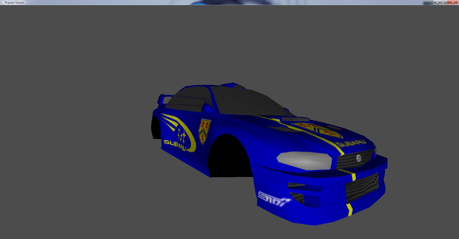
With great pain, I modelled a Subary Impreza WRX STi by pushing vertices, which was great fun and a good learning experience. The resulting polygon mesh is gross, but hey you have to start somewhere.
I still had no good texture for the wheels, however, when one day I saw a beautiful STi parked outside a restaurant right beside where I lived. I walked right into the restaurant and went from table to table until I found the owner, from whom I requested permission to photograph the car and its wheels.
Triangle-Batching Tool
Next, I wrote a tool to perform fanning and stripping on my modelled geometry, since on my GeForce 256 those were the fastest primitive types to use. They cut down both on bandwidth and transformation costs. (Nowadays different bandwidth limitations and large post-transform vertex caches frequently make it more interesting to use triangle lists instead, but that wasn't the case here.)
My tool used a a few simple heuristics to do its job. It would begin by first splitting any vertices as required to handle any texturing and normal requirements, since fixed-pipeline OpenGL doesn't support independent indexing for separate attributes. Next, it would create fans around any vertex used by 8 or more triangles:
Lastly, it would create strips by brute force, using a few heuristics. It would first examine each of the remaining unbatched triangles and locate the triangles with the lowest number of unbatched neighbours (treating any triangle pair with an edge in common as neighbours):
In the set of triangles with the lowest number of neighbours, it would iterate over each triangle's vertices and sum the number of triangles who used that vertex. It would the prefer triangles for which the sum was lowest:
The goal of this last heuristic was to make the algorithm try to strip "dangling triangles" on the edge of the mesh sooner, because these were more likely to become orphans later down. Without it, the algorithm frequently picked triangles in the "middle" of the mesh as starting points, which not only left a bunch of orphans on the edges but also sometimes "cut" an arbitrary stripped path from the center of the mesh to its edge, cleaving the space of available triangles for strips to be formed afterwards. I'm definitely not sure this last heuristic is advantageous in the general case, however - it may just be because of my input data. I would have needed to try my tool on more data sets to be sure.
Once the set of starting "problem triangles" was known, a simple brute-force search across all edges of the triangles in the starting set was made to find which edge and winding order yielded the longest strip. This strip was saved and the process was repeated until all triangles were batched.
The quality of the resulting strips and fans depended on the inputs:
Generally pretty crappy stripping, due to wonky input geometry. Note how the door and windows are a little better since I had an easier time modelling them, and as such the edge topology was much more intelligible.
Great fan and strips for the wheel geometry.
Run-Time Library
Afterwards, the idea was to get this geometry rendering as fast as possible. I wanted a few simple effects: transparency for the glass and a volumetric lighting effect for the headlights. (This last effect simply leveraged destination alpha with a special blend mode to lighten the frame buffer only where the dust particles appeared.)
I also included a real-time blurring test, done by rendering many lightly-transparent quads with the same texture, slightly offset from each other:
My goal with this project was to try out a simple method of minimizing graphics pipeline state changes while rendering a scene, since state changes were (and still are) quite expensive. In order to concentrate on this, I stuck to the OpenGL fixed pipeline model; the scene didn't really require anything programmable anyway, and that axis of exploration was sort of orthogonal to the state change issue.
The idea implemented by photon is simply that each logical object that requires rendering - be it a solid 3D model, a transparent 2D HUD element, whatever - registers a so-called "render key" with the rendering system. As far as the rendering system is concerned, this key is a kind of proxy for the rendered object; when rendering, all render keys in the system are traversed in a specific order outlined below, and they are all told in turn to render their payload. In this fashion the entire scene is rendered.
What's more interesting is what each render key contains, and how the rendering order is determined. When generated, a render key is made to contain a 32-bit "hash" of the rendering state required for the payload to be delivered. (More bits could be used for a more complex set of states.) For example, it might indicate that it requires a perspective projection, with client states enabled, texturing enabled, no texture coordinate generation, normal normalization on, lighting off, fog off, depth testing enabled, no culling, standard blending, all in the 2nd global rendering pass with a given texture ID, etc. This information is combined into the 32-bit key in such a way as to encode information relating to more expensive state changes in the high-level bits of the hash, and information pertaining to the least expensive state changes into the lower-level bits of the hash. For example, changing projection matrices is much cheaper than, say, enabling or disabling lighting wholesale; thus, the bit indicating whether a perspective or orthogonal projection is required would be placed somewhere in the least significant bits of the key, whereas the lighting-required bits would probably be placed somewhere in the middle of the key.
To render, all the the keys are sorted by value and traversed in the resulting order, from lowest value to largest value. Before calling the payload back, the rendering pipeline is setup as required by the information in the key. In a "normally-populated" scene, this means that all objects which require similar rendering states will be batched together. For example, all solid objects which require lighting, texturing, and fog will be rendered contiguously, and all objects requiring transparency, no depth test and an orthographic projection will also be rendered contiguously.
This has the benefit of minimizing the number rendering pipeline state changes, and also prioritizing them so that the most expensive ones are executed the least often. By comparing previous and next rendering keys, it also trivially allows the system to perform the absolute smallest amount of state change required by XORing the two keys to see which bits in the state have changed. This also implicitly does away with any "recall last state set by program and only set it if the value has changed" type of logic.
This arrangement also allows for a nice bit of decoupling, because the payload (be it procedural, like a HUD, or data-driven, like a player model) does not need to know "where" to insert inself into the traditional rendering buckets; it merely has to request the correct state when creating its render key. The payload code is made more elegant, because does not need to deal with any state setup; it only has to ask for the correct state when building its render key, and it can be assured the rendering pipeline will be setup correctly when the renderer calls back. As a bonus, all "stale state" problems (i.e. "I changed my object to render in a different part of the code/rendering pass/whatever, but now it doesn't render properly!") are also solved because each render key contains full information about the required state.
Conclusion
Though each part of the project was simple in isolation, they all worked great together and the final rendering path ran very fast, much fast than anything else I had tackled before.
Our IB school was tiny, with about 80 people (including staff) for 3 classrooms. Needless to say, space was at a premium, and so was born the premise for Crammed!: Tetris, but with people. You literally arrange people into as tight a space as possible, completing lines. I wrote this game in the spring of 1999, and created the small-scale animated graphics; a friend of mine, Olivier, made all the large-scale matte paintings. These drawings, which serve as backgrounds for the intro screen and the different levels, are more or less inside jokes referring to our school life.
The game is a simple Tetris clone, with a few variations. Other than the usual single-player mode, you can play 2-player versus, where completing two or more lines sends an equivalent number of "garbage" lines to your opponent, and 2-player co-op, where two players play simultaneously in a wider play area. You can also edit your own block shapes, as well as the probabilities of each block falling. (The game did not use the 7-bag system; this was still a bit before the big wave of standardisation across games.)
The game makes use of my handwritten font, created with FontX. All graphics were processed by E.
In 1999 I was still working quite a bit in mode 13h. I had written a few font libraries over the years, but for an upcoming project of mine, Crammed!, I wanted to use a digitized version of my handwriting. Thus, I wrote out most of the the ASCII table by hand and scanned the result. I tweaked a few of the characters in Photoshop on my dad's Mac, brought everything over to PC as BMPs, imported into E again, and converted all the characters to my custom sprite format.
Then, I wrote this little application, FontX, to manage the font that would be made up of these characters. FontX and its runtime library supported variable font sizes, variable-width fonts and tracking (global character spacing). It even supported kerning, though it did not do so by character pair; instead, it allowed each character to specify an amount of space to be applied to its left and right. There was also some measure of auto-fitting for all of the above given raw character data, to allow the user to concentrate on adjusting special cases to the baseline (mostly characters with descenders, though in the case of my handwriting each character was adjusted individually).
Though it was pretty simple, I consider this project a great success, because the fonts it produced looked great.