Saturday, April 23, 2011

Wireless NES Controller Doorbell (2008)

When we moved into our condo, we found a wireless doorbell module; the electronics still worked fine, but the case of the doorbell itself was broken beyond repair.  My uncle had recently scored a number of NES and accessories a a flea market, so I thought it would be neat to turn one of the controllers into a doorbell.

This is a pretty simple hack, since all I really did was replace the button from the original doorbell with the buttons from the NES controller.  Nevertheless, a short video about the doorbell on youtube has since garnered tens of thousands of views:
It's cropped up on random websites (even Gizmodo), and I am frequently asked for more details about the build, so here goes.

Just replacing the button would have been pretty simple, but I also wanted to add feedback to the user to tell them something was going on, since it's not immediately evident that the controller serves as a doorbell.  (After many years of use, however, I've only had one person knock because they were unsure what to do.)  I figured an LED that lights up when the user pushes a button should do the trick.

In order to figure out what the best way to wire all that up was, I wanted to trace out the doorbell emitter circuit  - the circuit behind the button you push to make the chime ring.  To do this, I took pictures of both sides of the circuit:
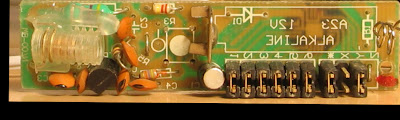
Top side of the circuit, with the components.

Underside of the circuit, with the button, a diode, a resistor, and a Circuit-On-Board (COB).

I loaded up those pictures as two layers in a Paint.NET document.  With a bit of reorienting/resizing, I was able to align the pictures so that they lined up with each other, and I could see either side of the board by toggling layer visibility.  (Note that one of the layers has to be flipped for this to work; you can tell from the pictures above that the word "ALKALINE" reads backwards.)  It helps to make the top layer partially transparent when doing this:
Both layers lined up.  You can tell that the components from the top side align with the solder pads on the underside.

Then, I used a small Wacom tablet to paint over the backside traces and components in a new layer:

Backside with hand-drawn traces.
Then, keeping the painted traces visible, I hid the circuit backside and showed the frontside:
Frontside with hand-drawn backside traces and components.
This is where you can tell that the job is made a bit more difficult because of the perspective foreshortening, since the red traces don't exactly line up with the component legs.  To mitigate this, I could have used a flatbed scanner to take the pictures (by putting the electronics on the bed), or perhaps taken the picture from a bit further back (at the expense of resolution).

Nevertheless, by twiddling the transparency of the front layer back and forth, I was able to trace the front-side components with the Wacom as well:
Traced frontside components.
And then, hiding everything but the hand-drawn stuff, I wound up with the following:
Final traced circuit.  (Image flipped horizontally from previous shots for legibility.)
From this point, I was able to transpose the circuit by hand onto paper:
Hand-drawn circuits.  The top circuit is the first jot.  The bottom one is the same circuit, but laid out differently to increase legibility.  The components I added are highlighted in red.
On the bottom circuit, you can somewhat delineate the stages of the circuit.  The battery is at the far left, supplying voltage to the the input stage (R3, S1, C1) and the COB.  S1 is read by the COB, and when a press is detected, the COB drives the transmitter stage on the far right.

To see how to merge the NES controller with this circuit, one needs to know a bit about how NES controllers are made.  It turns out to be quite simple: all the buttons are wired as independent inputs to a shift register.  Since the doorbell circuit has only one input, all I needed to do was to wire up all the controller buttons in parallel to S1, so that pressing any one button would close the circuit and ring the bell.

Additionally, to light up an LED when the button is pushed, I needed to wire up the LED (and a current-limiting resistor) in such a way that a voltage differential would exist across the LED when a button was pushed.  By analyzing the circuit above, it is possible to see that the input to the COB is active low - when S1 is closed, it brings the line read by the COB to ground.  (R3 acts as a pull-up resistor when S1 is open.)  Thus, an LED between the positive end of the battery (the net labelled N8 in the diagram above) and the input line read by the COB (net N9) will light up when a button is pressed.

Both these modifications are shown in the above diagram, in the red rectangle.

However, just adding the LED and the NES buttons in parallel caused a problem to occur: the doorbell wouldn't ring anymore!  This is because the buttons in the NES controller are made of little graphite pads that have a definite non-zero resistance, unlike a regular pushbutton.  (I seem to recall testing buttons up to a few kilohm.)  In effect, the NES controller buttons are creating voltage dividers with R3; if the resistance from the pushbuttons is too large, the voltage read by the COB does not drop low enough for it to detect a button press.

The first fix I made for this was to desolder R3 and replace it with a bigger resistor, to "recalibrate" the voltage divider to account for the higher resistance of the NES controller pushbuttons.  This required careful tuning, because the COB also requires a minimal amount of current to flow in for a button push to be detected; making R3 too large chokes off the current flow, once again preventing the doorbell from ringing.  Add to this the fact that the LED steals even more current from the COB and you have a tricky trial-and-error process to find values for R3 and the current-limiting resistor - values which allow the bell to ring, while allowing the LED to light up "sufficiently".

Once I had the electronics working, it was a matter of fitting everything into the controller casing.  Here are a few steps from the process:
The discombobulated controller.

Getting ready to make some space inside the case.

Part-way through cleaning up the case.

Testing the fit.

Another angle on fit testing.

Soldering up the buttons with the fire-starter I had at the time.

Buttons soldered up in parallel.

Testing the cutout for the chime circuit.

Final look, with the LED in the top-right.

Part-way through assembly.

Putting in the LED.

Mounted on the door using "temporary fixtures" which are still there three years later.

This worked great!  For six months.

When winter came, the bell stopped ringing - the resistance from the graphite pads inside the controller had risen, and the COB no longer detected button presses.  Tarnation!  The definitive fix was to use a time-proven trick to revitalize dead NES controllers, which is to use double-sided tape to affix little aluminum pads to the rubber behind the buttons, effectively replacing the graphite.  This dropped the NES button resistance by three orders of magnitude, and everything has worked since then.

Finally, I should mention that this was an afternoon hack that performed because I saw an opportunity to make something amusing.  People often point out that the buttons could make different sounds; that is quite true, and it would have made it even cooler!  Sadly, with the parts I had on hand, this would have taken quite a bit more effort.  But worry not!  Somebody has in fact built such a device, and you can see a video here.

Lessons Learned:

  • The internet is an awesome place - I never would have thought so many people would see the video.
  • The doorbell makes for a great conversation starter with delivery people.
  • Reverse-engineering circuit layouts can actually be a good time.

Monday, November 15, 2010

Digital Chromatic Guitar Tuner (2008)

Back in 2008, we organized a family gift exchange for Christmas, and one of the items on my brother-in-law's want list was a chromatic guitar tuner for his band Guajira.  Seeing this, I began thinking about how one would go about building such a device, and, thinking it would make a cool Christmas vacation project, I decided to try my hand at it.  After a bit of research, I started designing on December 19th; after much programming, building and testing later, I finished with moments to spare on December 24th.


Here is the video I posted shortly thereafter:


Over time the video has elicited many technical questions from viewers, questions which I couldn't answer in full detail until now for reasons unnamed.  I'll try to provide a bit more detail than usual in this writeup, but keep in mind this project is almost two years old so the details are getting hazy.  :P  Also, since I no longer have the device in my possession, having given it away at the gift exchange, I'm unable to take new pictures of it, and I'm stuck with cruddy webcam pics.


The Tuner


As seen in the video, the device has a few functions.  It accepts analog input from a standard 1/4" TRS jack, performs monophonic pitch detection on it, and either displays tuning information or outputs MIDI signals based on the detected pitch.  Tuning can be adjusted by moving A up or down a few hertz from 440.  There is a bypass switch, a backlight switch for the LCD and a contrast ratio pot; the whole thing runs on either DC power or a 9V battery.


You can get the code from the following links:


For the Google Docs link, you can use the File/Save option to save the archive to your disk.

The Electronics


First off, I am far from being proficient with hardware design; my experience is quite limited, and I'm much more comfortable with digital than analog.  I didn't have an oscilloscope when I built the tuner, so I did a lot of fiddling with component values using just a multimeter and a few speakers to listen for noise.  (I've since acquired and assembled a DPScope, they're excellent.)  As such, the design process was very much empirical, and I had fun swapping parts to see what worked best without the worry of frying a few pennies' worth of electronics.


Also, missing from these schematics is an Arduino.  I used a Real Bare-Bones Board from Modern Device, which I recommend; cheap, tiny, easy to assemble.  Signals named A5, D4, D5, D6 etc.  in the following schematics connect to the pins with the same name on the ATmega168.


There were a few LED connections and simple pushbuttons, whose circuitry I didn't outline here.  If you're wondering how to connect such devices to an Arduino, I would suggest the Arduino Playground as a starting point - it's a great wiki.


  The Power Stage

The power stage, which provides regulated 9V power to the rest of the circuit.


POWERSW is the system's power switch, which does its job by connecting the system ground to the power jack's ground pin (pin 3 on DCEXT).


In the case where no external jack is connected, DCEXT's pin 2 is connected to pin 3; the LM317T remains unused, and the 9V battery directly feeds VCC and GND.


In the case where an external power jack is connected, DCEXT's pin 2 remains floating, which disconnects the battery ground from the system.  The LM317T turns on and regulates outside power; voltage is adjusted to 9V using VADJ, as per the 317's datasheet.  CFILTPOWER is there to smooth out ripple, acting as a low-pass filter.  I had a 100uF lying around so I used that.  (The LM317 datasheet recommends 10uF or more.)


What I learned:
  • The battery leaks 6mA through R2 and VADJ, which is quite crappy.
  • You mileage may vary when adding a filtering capacitor before the LM317T; I found it made no discernable difference in this case.
  The Input/Bypass Stage


Input and bypass.


Well, it doesn't get much simpler than this: a dual-pole, dual-throw switch that either routes the signal from the input jack to the circuit or right back out, like a 2-way multiplexer.


What I learned:
  • The foot switch was difficult to source, and once I found an appropriate one, it took up LOTS of space in the case - on the order of two cubic inches.  I hadn't really planned for this.
The Buttons

Button wiring; not much to see here, just a simple pull-up resistor setup.  As reader Geoff Steele pointed out, you can also simply use the ATmega's internal pull-up resistors.

    The LCD Stage

    LCD connections.

    Once again, pretty standard stuff.  The LCD I used had a backlight, hence BACKLIGHTSW.  Contrast adjustment is done using RCONTRAST, on pin 3.  Pins 4, 6, 11, 12, 13 and 14 form a 4-bit data connection to the Arduino, as described on the Arduino LiquidCrystal page.


    What I learned:
    • The cheap surplus MTC-16205D LCD I used required some extra "convincing" to boot up properly.  I included the LiquidCrystal library directly in the PDE and modified the source to get it working.
      The MIDI Stage

    MIDI connector connections.

    More standard fare; I recommend the ITP page about MIDI output from Arduino, it's great!

      The Amplification Stage

    The amplification stage, which takes the input from the guitar and feeds it to the Arduino.  (See note below about INPUTCOUPLING capacitor, I think I had the wrong value marked down.)

    This stage is the one I spent the most time trying to get right, and (I'm guessing) probably the portion of the circuit which is of most interest to the people trying to build something similar.  I'm positive there are many grievous design errors in here, but in the end I got it working well enough.

    Overall, what this circuit does is take the input, adjust its volume (VADJ), amplify it (the LM386), and convert it to a form which the Arduino can sample (R7/R8/D1/D2).

    I began with the application entitled "Amplifier with Gain = 200" from the LM386 datasheet:
    • Volume adjustment is done using VADJ1 as a voltage divider.  I preferred this approach over adjustable amplification gain because the physical mapping of "angle of the volume potentiometer" to "amplification volume" was easier to control this way; judging by the LM386's typical applications, this seems to be an oft-favoured way of doing things.
    • The LM386 is setup as a fixed gain amplifier, whose gain is adjusted to 200 using CFILT3, as per the datasheet.
    • The output is fed through a low-pass filter built using CFILTAUDIO and R6; this rejects unwanted noise from the amplifier.  Without it, you can hear AM radio faintly, and there is a lot of crackle in the amplified sound.
    • An output coupling capacitor, OUTPUTCOUPLING, blocks any DC bias at the output of the amplifier, preventing it from leaving that stage and entering the following portion of the circuit.  (If a speaker was connected directly to the output of the amplifier, DC would flow through the speaker's coils, which are delicate and may heat up.  Here, instead of a speaker, we have an Arduino; more on this below.)
    You'll also note that I made a few modifications:
    • I added R5 to set the minimum amplification level.  R5 effectively create a "floor" for the voltage divider formed by R5 and VADJ1.
    • I added the INPUTCOUPLING capacitor to fix a buzzing problem; I think I wound up using a bigger value than 0.011uF, however, since that's an unusually small value for a coupling capacitor, one which I think might have filtered the signal a bit too much.  Much like the output coupling capacitor, this prevents DC from entering the op-amp (LM386) and being amplified, offsetting the output signal.  I distinctly recall trying multiple values on for size here.
    • Instead of connecting a speaker to OUTPUTCOUPLING, I connected an analog input on the Arduino so I could sample the signal.
    There is a small problem here: you can't just take the output from the LM386 and connect it to the Arduino pin.  This is because the amplifier, as set up, outputs signals from 0V to 9V, centered around 4.5V; under normal conditions, an Arduino can only sample analog signals between 0V and 5V, so a direct condition would not only saturate the ADC but likely damage the Arduino's input.

    To rectify this situation, we have to do two things.  Firstly, we can add D1 and D2 as shunt diodes to clip the signal to 5V and 0V, respectively.  In practice, the forward bias of the diodes allow the signal to exceed the allowed range slightly, but the excess shouldn't damage your Arduino.  I used fast-switching 1N914 diodes, which I just realized have a forward bias voltage of 1V; this means the signal can still range from -1V to 6V, which is probably a bit much to be safe.  Nevertheless, I've had no problems so far... knock on wood.  :P

    The second thing we must to is a bit trickier.  The output of the LM386 centers around 4.5V, which is half its supply voltage.  The Arduino, however, has a mid-range input of 2.5V, which is half-way between 0V and 5V.  If the Arduino just sampled the signal as clipped by the diodes, we'd be sampling the amplified signal in an asymmetric fashion, with 4.5V of range on the negative side (i.e. anything below 0V on the amplifier input will be below 4.5V on the output) but only 0.5V of range on the positive side.  This means that the Arduino would get a skewed view of the waveform from the LM386, which would make it difficult for us to have an accurate "big picture" of the waveform for frequency analysis.

    To fix this, we must add a DC bias to the signal, to "re-center" it around 2.5V.  This is done with the help of R7 and R8, which form a sort of voltage divider.  Since R7 and R8 have the same value, when no AC is coming through the coupling capacitor, the voltage at the Arduino pin is 2.5V.  When the LM386 is busy amplifying a signal, the AC component of the amplifier's output makes it through OUTPUTCOUPLING, nudging the rest point of 2.5V up and down, if you will.  (It is important to use large values for R7/R8 in order to raise the cutoff frequency of the high-pass filters they form with the OUTPUTCOUPLING capacitor.)

    You may wonder what we do about scaling the range of the signal.  The answer is: nothing, VADJ1 takes care of that for us.  Since different guitar pickups have different signal levels, on the tuner I built, the user adjusts VAJD1 using a potentiometer.  Software-driven LEDs indicate amplified (and sampled) signal strength for calibration.


    What I learned:
    • Despite warnings from my E&CE241 teachers and lab instructors to the contrary, as long as you keep the datasheet warnings in mind and your finger not too far from the kill switch, it is perfectly fine to try various component values in your circuit.  In fact, it's fun and instructive, and I plan to do more of it in the future.
    Notes on the Circuit as a Whole

    Seeing as how it's performing signal analysis, the tuner is fairly sensitive to power supply noise.  About a year after the tuner was made, I took it in for a "service call".  The unit sometimes no longer detected pitch properly; after some testing, I realized this only occurred if the LCD backlight was on and an external power adapter was used.  It seems that when the LCD backlight is on, the extra load on the power supply stage increases the ripple which makes it through to the amplifier stage and Arduino supply (which, in turn, probably affects the reference voltage of the ATmega168's ADC to some degree, even though the Arduino has its own regulator).  My hypothesis is that this is due to failure of some kind in the power supply filtering; possibly my recycled 100uF capacitor gave up the ghost or otherwise deteriorated; perhaps my soldering was suboptimal; perhaps there are gremlins in the box.  In any case, this is very similar to what occurred on a breadboard when I accidentally knocked the 100uF capacitor out.

    The Software

    The software does a few things.  I won't really discuss the pushbutton logic and so on here, since there is a lot of documentation available about that.  The two things I get the most questions about are the pitch-detection algorithm and the method I used to output slim vertical bars on the LCD.

    How to Perform Pitch Detection


    I tried a few "heuristic" algorithms - counting zero crossings, analysing the first-order derivative, and so on - but these often depended on the shape of the signal, which gave erratic results.  (Even a single vibrating string has multiple harmonics which make such approches difficult to work with.)  I wound up settling on a home-grown variation (and simplification) of an algorithm called YIN, which you can find described here.  Based on autocorrellation, this algorithm worked much better than all other approaches.  However, as you might tell from the paper, it is relatively expensive in terms of computation and memory, at least as far as an ATmega168 goes.  (Newer Arduinos now use the ATmega328; double the SRAM goes a long way, but you might be constrained by the speed at which you can process the data.)  The challenge was to adapt YIN to make it work with a 16MHz CPU that has no FPU and a few hundred bytes of available RAM.

    I won't explain the full details of YIN here, but I will explain the gist of it, to show how I adapted it for the Arduino.  Autocorrellation-based approaches are actually reasonably simple to visualize.  Given a quasi-periodic signal like that produced by a vibrating string, the idea is to take the original waveform:

    The basic sampled signal.

    And then, we create a virtual copy of the signal, shifting it over a bit:
    Copy of the original signal.

    Then, we compute some function of the area between the two resulting signals, shown in purple below:
    The idea is to keep sliding the copy over until the area between the two resulting signals is minimized.  Notice how the red copy keeps sliding over to the right, and how it gets closer and closer to "matching" the blue copy again.
    In practice, the steps are much smaller.  I made them a bit larger above to demonstrate the idea.  However, since we're getting quite close to the red waveform overlapping the blue one again, for the purposes of illustration, let's reduce the step size a bit.  (Again, the actual algorithm tries many, many small steps.)

    (Pretty close here!)

    As you can see, in the third picture above, the two curves came pretty close to overlapping.  That corresponds to the moment where the purple area - a function of the area between the curves - was minimized.  Once you figure out the offset between the curves for which this area is minimized, you can calculate the corresponding pitch with the following simple equations:
    So that's the general idea.  But how do we make it run on Arduino?  Put another way: what is it that's prohibitively expensive about YIN and prevents it from running on the ATmega168?  In practice, I found the two constraints were the time spent computing the value of the difference function (related to the "size" of the purple area above), and keeping a tight reign on the memory requirements of the sampling buffer.

    The first hurdle you run into is floating-point math support; simply, there is none on the ATmega168, so you have to give up on floating-point math in any performance-critical portions in the code.  I used fixed-point math where I required fractional quantities in the code.

    Next, as with most every decision when building gizmos, you have to start thinking about tradeoffs.  The difference function used by true YIN works by iterating over all samples in a given window, subtracting the value of the red curve from that of the blue curve and squaring that difference, summing all values thus obtained.  The first change I made was to give up on the squaring operation, which required a lot of expensive multiplications, and instead simply compute the absolute value of the difference at each sample:
    where tau represents the offset at which the difference function is being evaluated.

    In many ways, the revised version is related to the average magnitude difference function (AMDF) mentioned in the YIN paper, only without the averaging operation.  Losing the squaring operation may introduce inaccuracies in our detection, but it keeps the general shape of the resulting function looking pretty close to the original while giving us huge improvements in executing speed, so it works out.  (Critically, the minima and maxima of both equations occur for the same values of tau.)

    That really helped speed up execution, but it was still too slow and memory-intensive.  As it turns out, if you can reduce the size of your buffer, you also gain in computation time, because you have fewer samples to process - two birds with one stone!  So the next step was trying to figure out a buffer size for which the computation was fast enough, while maintaining the required pitch detection precision.

    By "maintaining the required pitch detection precision", I mean that as the wavelengths get shorter and shorter (i.e. as pitch gets higher), a period will take up fewer and fewer samples in our buffer.  See the following exerpt from a small helper worksheet I made:


    Frequency (Hz) Cpu Cycles Per Period seconds per period samples per period
    A 55 290909.09 0.01818 174.83
    A# 58.27 274581.62 0.01716 165.01
    B 61.74 259170.54 0.01620 155.75
    C 65.41 244624.41 0.01529 147.01
    C# 69.3 230894.7 0.01443 138.76
    D 73.42 217935.57 0.01362 130.97
    D# 77.78 205703.79 0.01286 123.62
    E 82.41 194158.52 0.01213 116.68
    F 87.31 183261.24 0.01145 110.13
    F# 92.5 172975.58 0.01081 103.95
    G 98 163267.21 0.01020 98.12
    G# 103.83 154103.72 0.00963 92.61
    A 110 145454.55 0.00909 87.41
    A# 116.54 137290.81 0.00858 82.51
    B 123.47 129585.27 0.00810 77.88
    C 130.81 122312.21 0.00764 73.5
    C# 138.59 115447.35 0.00722 69.38
    D 146.83 108967.79 0.00681 65.49
    D# 155.56 102851.9 0.00643 61.81
    E 164.81 97079.26 0.00607 58.34
    F 174.61 91630.62 0.00573 55.07
    F# 185 86487.79 0.00541 51.98
    G 196 81633.6 0.00510 49.06
    G# 207.65 77051.86 0.00482 46.31
    A 220 72727.27 0.00455 43.71
    A# 233.08 68645.4 0.00429 41.25
    B 246.94 64792.63 0.00405 38.94
    C 261.63 61156.1 0.00382 36.75
    C# 277.18 57723.67 0.00361 34.69
    D 293.66 54483.89 0.00341 32.74
    D# 311.13 51425.95 0.00321 30.91
    E 329.63 48539.63 0.00303 29.17
    F 349.23 45815.31 0.00286 27.53
    F# 369.99 43243.9 0.00270 25.99
    G 392 40816.8 0.00255 24.53
    G# 415.3 38525.93 0.00241 23.15
    A 440 36363.64 0.00227 21.85


    Prescaler 7


    ADC Divider 128


    Clk/sample 13


    F_CPU 16000000


    SampleRate 9615.38


    See at the end there, around the 440Hz mark, rounding up the 21.85 gives 22, and rounding down the 23.15 gives 23 - that means that using integer buffer offsets (integer values of tau) in the formula above, it would become difficult to differentiate consecutive semitones starting around that A.

    One way to increase the precision would be to reduce the prescaler value on the ADC and sample twice as often, which would mean reducing the speed of the code by half and growing the memory by a factor of two.  But what is the exact buffer size we're talking about here?  What would be the minimal buffer size required to work with the YIN and the frequencies we want to analyze?  Well, we need a minimum of two full periods being sampled, in order to be able to copy the first period over the second.  Looking at the above table, if we set our minimal frequency to 55 Hz, 175 samples are required to sample a full period, so the minimum size of the buffer would be 350 samples.

    The above table shows that these settings are sufficient for coarse precision, around 100 cent of a semitone at the highest frequencies.  This is what the code uses for perform pitch detection when in MIDI mode, because it is important to reduce latency (and thus minimize computation).  However, 100 cent is hardly sufficient to perform precise tuning of guitar strings, so we must dive further.

    I use another trick from the YIN paper: sub-sample interpolation.  The idea is simple.  In practice, the offset at which the difference function is minimized will never be an integer value; it will be a fractional value, meaning that you have to shift the red copy of the waveform over by a fractional number of samples for the two copies to line up perfectly.  Unfortunately, we only sampled the signal at specific intervals, so in order to be able to "resample" the signal at fractional offsets, we reconstruct an approximation of the original, true, analog signal by interpolating between the samples we took.  Where YIN uses quadratic (second-order) interpolation, however, I was limited to linear (first-order) interpolation by the processing power.  Nevertheless, this provides greatly-enhanced precision.

    In the end, to get everything integrated and running, I wrote a small set of classes that allowed me to profile single statements as run on the actual hardware.  I also used avr-objdump to disassemble the code produced by the compiler and understand where the inefficiencies were.  (There was no need to hand-assemble code; the compiler does a fine job as long as you use the correct datatypes.)  I fiddled around with the sampling precision (the ADC on an ATmega168 can sample up to 10 bits of precision), the minimal detection frequency, and the interpolation step size a great deal until I settled on 8-bit samples, a minimum frequency of 60 Hz, and a prescaler value of 7, for a final buffer size of 321 bytes.  The sub-sampling code uses fixed-point math with a 5-bit fraction, and it solves up to the least significant bit when finding the minimum in the difference function; thus, the tuner has a theoretical accuracy of 1/32th of a sample, or approximately 2.4 cents of a semitone at 440Hz (3.8 cents at 880Hz).

    (The code applies a small amount of low-pass filtering to the final computed pitch value in order to smooth out the display on the LCD.)

    The LCD Driver

    Rendering the thin vertical bars on the LCD is actually not very complex.  Most LCD drivers have a small area of memory called CGRAM, short for Character Generator Random Access Memory, which allows you to create a few custom characters for display.  Since the display matrix of the LCD I used was 5x7, I merely created five custom characters, each which a different column of dark pixels.  Turning on a given column of pixels then becomes the simple matter of writing the correct custom character to that location on the screen.

    Scary Pictures

    As mentioned above, about a year after hacking this thing together, I took it in to replace the battery.  By this point, my digital camera was repaired, so I snapped a few glorious pictures of the complete mess that it is.


    Sunday, August 22, 2010

    Digital Fluid (2000)

    After spending time teaching my computer how to solve Rubik's cubes, I started thinking about writing something that would cater to my lifelong fascination with gooey matter and infinitely-derivable functions.  The first generation of GPUs had just come out (hardware transformation and lighting, oh my!) and it was time to put my 450$'s worth of graphics hardware to work.  Other than playing games, of course.  Ahem.

    By tinkering over the course of a few nights, I wound up writing this little fluid simulation.  As it turns out, most of the computation performed wound up on the CPU, so it was taxing little more than the transfer rate of my AGP 4x bus.  However, it does shun vendor-specific extensions in favor of multipass rendering to layer the specular highlights onto the texture map.

    The fluid patch is implemented using a height field; normals and other epiphenoma are derived from the vertex positions.  Texture coordinates are calculated using Snell's law, by putting the texture on a virtual plane behind the fluid patch.

    The simulation itself isn't really that interesting from a mathematical standpoint - I was just experimenting, so all the code is ad hoc.  The positions are animated using different models.  For liquids, linear combinations of many simple closed-form sinusoidal decay solutions are used.  For the gooey-looking ones, a simple spring/damper model is used.

    (Browsing this code ten years later, I can say that this being my second C++ program, the code stank a bit less than the cube solver. :P )

    Be sure to pick HD if available over your connection... the low-resolution version looks like a tie-dye cow.


    Lessons learned (or points confirmed):
    • Programmer art sometimes far outlives its intended longevity...  As of this writing, 10 years later, I still haven't replaced that Paint-produced bitmap.
    • Stuff doesn't necessarily need to be complicated to look decent.  In fact, the simpler it is, the easier it usually is to tweak the way you want it.  (Recall that this was in year 2000; register combiner cards were still quite mainstream.)

    Rubik's Cube Screen Saver (2000)

    Around the same time I was given my first copy of Visual Studio, I bought the OpenGL Superbible.  Feeding these two items through the transfer function of my deranged brain, I wound up brewing the following program as a first foray into both the worlds of C++ and modern API-based graphics programming (as opposed to writing to the metal).

    The program solves rubik's cubes, bouncing them around the screen:


    The algorithm is the same I first learned to use when solving the cube by hand - the original Singmaster method - and it's far from optimal.  I recorded sequences of moves interactively using a built-in "move editor", then wrote code that analysed the state of the cube and chose the algorithm to play back.  The debug mode output looks something like this:


    Lessons learned:
    • As a first contact with the world of hardware abstraction layers, in terms of API design, OpenGL and GLUT are infinitely friendlier than DirectX 5.0.
    • Do read your employment contracts closely.  I got into somewhat serious trouble for posting a copy of this on NeHe, believing the IP belonged to me since I had created it on my own time.  Not so.
    • A 2,300 line switch statement does not constitute "artificial intelligence".  (I still laugh this one today.  In my defense, it's not because I didn't know better in terms of design; it's more that I was still learning so much about the language at the moment that there were more pressing points than learning about the constructs which would have enabled me to organise my code in a cleaner fashion.)